A sewage treatment plant that handles average flow on paper can still fail during production peaks, winter temperatures, sludge dewatering or equipment maintenance. By the end, you will have a practical checklist for defining the design basis, selecting the process, testing site constraints and setting operating requirements that remain workable after commissioning.
Key takeaways
- Size for peak hourly flow and the strongest credible sewage load.
- Verify the discharge consent, reuse standard and receiving environment before selecting treatment.
- Compare energy, chemicals, sludge, maintenance and operator demands over the plant’s design life.
- Use commissioning data to prove flow, effluent quality, controls and sludge performance.
Build the Design Basis From Flow, Load and Seasonal Conditions
A design basis should describe the strongest credible sewage condition over the design horizon, not merely today’s average. Establish average daily flow from metered records, then calculate peak hourly flow and the peak factor: peak hourly flow divided by average daily flow.
Check per-capita contribution against measured occupancy, planned population changes, infiltration and inflow, water-saving fixtures and seasonal visitors.
Record a mass-load envelope from flow-proportional samples taken in dry and wet weather and during production or cleaning peaks:
- BOD, COD and TSS
- Ammonia, total nitrogen, phosphorus and alkalinity
- pH, temperature, salinity or conductivity, FOG and toxicity indicators
- Pathogen indicators and industrial cleaning chemicals
Keep domestic sewage and trade effluent identifiable in the records; a dilute composite sample can hide a toxic or high-strength industrial discharge that belongs in an ETP or pretreatment system.
Base nitrification on the coldest expected wastewater temperature and the specified effluent ammonia limit, not the annual average. Confirm solids-retention time against winter nitrifier growth, and include returned sludge liquors in the nitrogen balance. Size the hydraulic profile for peak hourly flow through every restriction and downstream level condition.
If equalization is needed, specify mixing, turnover, level control and odour control; otherwise the tank can turn septic and deliver a concentrated shock load. Make acceptance testing cover cold, peak-load and dewatering conditions, with defined duration, samples and energy and chemical measurements.
Confirm the Wastewater Stream and Treated-Water Endpoint
A plant for domestic sewage is not automatically suitable for industrial wastewater. Compare each stream’s mass-load envelope, not just its flow: record BOD, COD, TSS, pH, ammonia, salinity, oil and grease, temperature, toxicity and cleaning chemicals across production and shutdown cycles. A dilute average sample can hide a peak that poisons biology or overloads aeration.
Keep streams separate when industrial wastewater contains solvents, metals, high salinity, extreme pH, disinfectants or variable production loads. Route it to an effluent treatment plant or defined pretreatment before biological treatment. Combine it with domestic sewage only after compatibility testing confirms that the mixture will not inhibit nitrifiers, upset pH or create an unmanageable sludge.
Choose the endpoint before selecting the process. Write the required limits into the design basis:
- Sewer discharge: meet the receiving sewer’s consent limits for BOD, COD, TSS, pH, temperature and prohibited chemicals.
- Surface-water discharge: meet the discharge permit, including ammonia, nutrients, pathogens and toxicity.
- Toilet flushing, gardening or cooling-tower reuse: specify filtration, disinfection, residuals, salinity and pathogen limits for that use.
A nominal chlorine dose is not proof of pathogen control; verify contact time, mixing and demand, or validate UV dose against UV transmittance and solids carryover.
Compare Treatment Processes Against Lifetime Operating Demands
Compare processes over a 10–20-year operating record, not one successful effluent sample. Score energy, operator workload, footprint, resilience, sludge management, chemical use, maintenance access and the consequence of failure at peak flow and the coldest wastewater temperature.
| Process | Lifetime strengths | Lifetime liabilities |
|---|---|---|
| MBBR | Compact, robust against load variation, and less vulnerable to biomass washout | Aeration remains significant; media screens, retention devices and carrier loss require inspection |
| SBR | Few tanks can provide biological treatment and settling through timed cycles | Uneven inflow needs equalization; valves, decanters and controls create maintenance points |
| MBR | Produces low-suspended-solids effluent in a small footprint | High aeration demand, membrane fouling, chemical cleaning and eventual membrane replacement |
| Activated sludge | Flexible nutrient-removal configurations and familiar operating practice | Blower electricity, clarifier performance and sludge recycling drive operating cost |
| Trickling filters or RBCs | Lower aeration demand and simpler biological operation | Hydraulic distribution, odour, media condition and lower process control can limit performance |
Price the sludge route before selecting the reactor. Compare sludge production, polymer demand, dewatering cake quality, hauling frequency, disposal acceptance limits and beneficial-use options; cheaper aeration can create a higher total cost. Design nitrification for winter temperature and required ammonia, then verify blower turndown, dissolved-oxygen control, instrumentation fallback and standby capacity.
Include hydrogen-sulfide source control, ventilation zoning and corrosion-resistant materials where septic sewage is expected.
Test the Site, Hydraulic Profile and Plant Format Before Design
Start with a surveyed site plan, not a tank catalogue. Record property boundaries, road access, ground levels, soil conditions, flood risk, power availability, discharge point and the elevations of every existing sewer. A plant that fits in plan can still fail if trucks cannot remove sludge or gravity flow cannot reach the outlet.
1. Map the hydraulic profile for peak-hour flow. Include headloss through screens, pipes, reactors, filters, UV channels and the final effluent structure. Leave margin for fouling and raised downstream levels; otherwise extra pumping becomes a permanent energy cost.
2. Quantify infiltration and inflow separately from sewage generation. Inspect manholes during rain, check groundwater levels and trace roof or storm connections. An equalisation tank can absorb timing variation, but it cannot correct an undersized outlet or a leaking collection network.
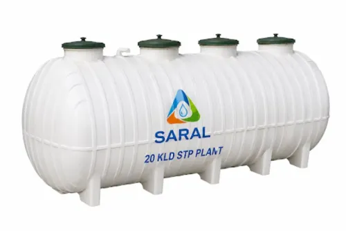
3. Compare a site-built plant with a packaged FRP plant against access, footprint, foundation loads, crane clearance, corrosion exposure and future expansion. Choose FRP only after confirming that replacement tanks, blowers, pumps and control panels can enter the site.
4. Test maintainability on the drawing: provide safe walkways, lifting points, isolation valves, drain-down routes, sampling points and room to remove screens, diffusers, membranes and sludge equipment. Ask Terra Ecosystems Pvt Ltd to show these maintenance clearances in the layout, not merely list equipment.
5. Fix odour-control zones, ventilation, hydrogen sulfide monitoring and corrosion-resistant materials before construction. Wet wells, headworks and equalisation tanks can damage concrete, instruments and electrical equipment when gas control is added too late.
Related products
 | SEWAGE TREATMENT PLANT We has many years of Sewage Treatment Plant Solution experience in the design, construction, and operation of wastewater treatment plants, we are... View product → |
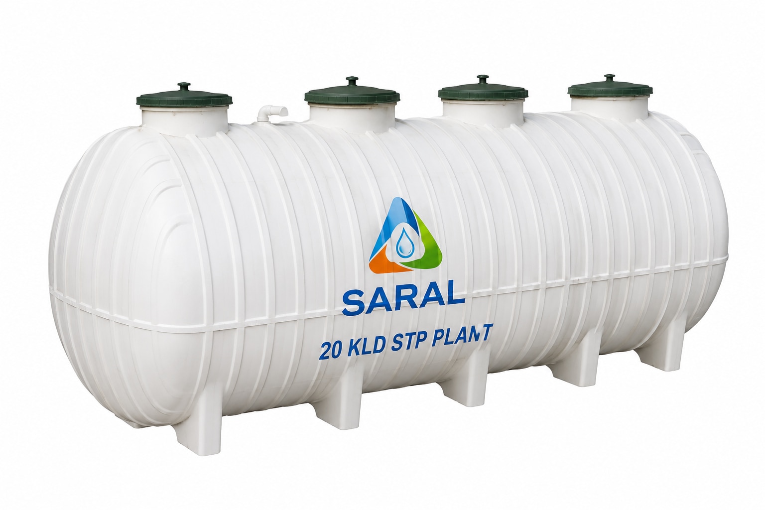 | PACKAGED SEWAGE TREATMENT PLANT PACKAGED SEWAGE TREATMENT PLANT SARALTM FRP STP is a prefabricated, decentralized onsite sewage treatment system designed in accordance with CPHEEO guidelines for residential,... View product → |
Specify Controls, Nutrient Balances and Sludge Handling Together
Close the oxygen, alkalinity, carbon and sludge balances before selecting automatic controls. Nitrification consumes alkalinity; denitrification needs usable carbon, while internal recycle can return nitrate and dissolved oxygen to anoxic zones. If readily biodegradable carbon is low, price chemical carbon or change the process configuration rather than chase nitrogen limits with extra aeration.
| System | Specify together | What failure costs |
|---|---|---|
| Aeration and nutrient removal | Blower turndown, air-flow meters, diffuser-cleaning access, duty/standby blowers and dissolved oxygen control; verify process-water oxygen transfer, not clean-water figures. | Excess air wastes electricity; inadequate air suppresses nitrification and leaves ammonia. |
| Recycle and sidestream loads | Include nitrate, ammonia, alkalinity and flow from thickening, digestion and dewatering in the liquid mass balance; schedule high-strength returns. | A dewatering campaign can create nitrogen peaks and defeat denitrification. |
| Sludge, odour and corrosion | Compare sludge yield, polymer demand, dewatering, hauling and disposal; provide covered septic zones, ventilation and H2S control where needed. | Wet sludge raises hauling cost; sulphide attacks metal and creates odour. |
Use online DO, ammonia, nitrate, pH, flow and suspended-solids instruments with cleaning, calibration and sample-flow checks. Give every critical loop alarm limits, local manual control and a safe fallback for sensor failure. Test winter nitrification, peak loads, standby changeover, dewatering, energy use and chemical consumption before acceptance.
Make Commissioning Prove Long-Term Performance
Do not place the plant into routine service until performance testing proves it can meet its limits under representative conditions, not only during a warm-weather, steady-flow demonstration. Tie the acceptance protocol to the Consent to Establish, Consent to Operate and State Pollution Control Board requirements.
1. Define test loads, sampling points, laboratory methods, duration, exclusions and pass/fail limits for flow, BOD, COD, TSS, ammonia, pH and disinfection.
2. Test steady flow, peak hydraulic load, peak organic load and the coldest expected wastewater temperature. Confirm nitrification, aeration response and effluent compliance after stable operation.
3. Operate pumps, blowers, mixers, dewatering equipment, alarms and standby changeover under simulated failures. Record energy, chemical, polymer and sludge-hauling requirements.
4. Challenge every critical online instrument for fouling, calibration drift and lost sample flow. Verify alarm limits, local manual control and the safe fallback mode.
5. Require operating records, maintenance schedules, spare-parts lists and operator training before handover. Track sludge cake quality and disposal acceptance, not just reactor performance.
Frequently asked questions
What information belongs in a sewage treatment plant design basis?
Record average daily flow, peak hourly flow, peak factor, pollutant loads, seasonal conditions and the strongest credible future condition.
How do you choose a sewage treatment process for long-term efficiency?
Compare each process by energy use, chemical demand, sludge production, maintenance access, operator workload and required treated-water quality.
What should you check at the site before designing the plant?
Check wastewater sampling, available area, ground conditions, flood risk, inlet and outlet levels, hydraulic losses, access and the required plant format.
Why must sludge handling be designed with the treatment process?
Biological treatment creates sludge that needs thickening, dewatering, storage, transport and lawful disposal, so these systems must match expected production.
What should commissioning prove before handover?
Commissioning should verify hydraulic capacity, aeration and controls, nutrient removal, treated-water quality, sludge performance and stable operation under representative loads.