A clarifier separates wastewater solids only when particle size, density, flow conditions, and sludge withdrawal work together. By the end, you will be able to trace the separation path, judge whether your solids will settle, compare design figures, and identify the operating conditions that produce cloudy effluent.
Key takeaways
- Run a settling test before selecting clarifier capacity.
- Compare surface overflow, solids loading, detention time, and weir loading.
- Use inlet energy dissipation to limit short-circuiting and dead zones.
- Check sludge blanket depth and rising solids when effluent turns cloudy.
How solids move through a clarifier
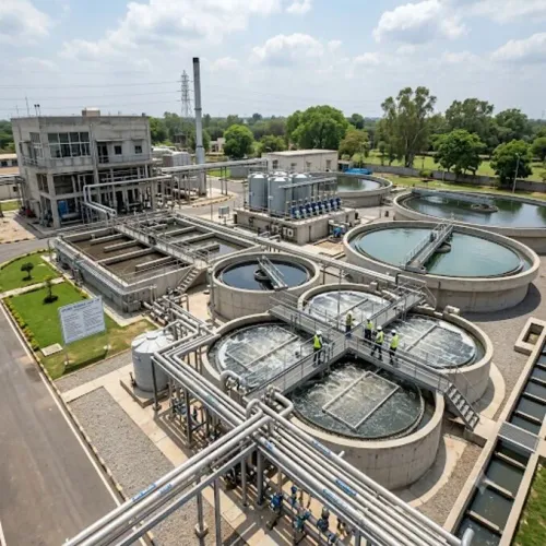
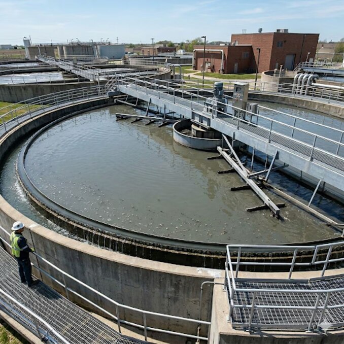
Influent enters the clarifier through an inlet energy dissipation area that reduces momentum and spreads flow across the basin. This prevents short-circuiting, density currents, and dead zones that reduce the effective settling area.
- In the inlet or reaction zone, coagulated and flocculated particles meet and form larger, heavier flocs. Chemical addition and mixing occur here when the process requires them.
- In the settling zone, flow moves slowly enough for gravity settling to separate solids from liquid. Dense suspended solids descend, while lighter material can rise and become scum.
- At the bottom, settled solids accumulate as sludge. Scraper arms move this sludge toward a hopper or collection point, where a pump or valve removes it before the blanket becomes too deep.
- Near the top, clarified liquid moves toward the effluent launder and passes over weirs. The weirs must distribute withdrawal evenly; an overloaded or uneven outlet creates local velocity that pulls solids into the effluent.
This is the core of solid-liquid separation: solids leave downward, and treated liquid leaves upward or outward. Excessive inlet energy, peak flow, a rising sludge blanket, or poor sludge withdrawal can carry settled material through the outlet instead. In a secondary clarifier, return activated sludge also changes internal solids circulation and the blanket’s behaviour.
What clarification removes—and what it cannot remove
A clarifier removes settleable particles and flocculated suspended solids by gravity. It produces a clearer upper liquid and a concentrated sludge layer, but it is not a general-purpose contaminant remover. Dissolved salts, soluble organics, and stable colloids pass through unless coagulation and flocculation convert them into settleable floc.
| Process | Main job | Handles best | Cannot replace |
|---|---|---|---|
| Clarification | Separates solids by gravity | Settleable particles and formed floc | Dissolved contaminants or buoyant solids |
| Thickening | Raises solids concentration in sludge | Sludge volume reduction before treatment or dewatering | Producing a clear effluent |
| Filtration | Captures particles as liquid passes through a medium | Fine suspended solids that escape settling | Dissolved salts without a specialised medium |
| Flotation | Lifts solids with attached air bubbles | Oil, grease, algae, and buoyant or slow-settling solids | Most dense, readily settleable solids |
A clarifier therefore needs another process when the target contaminant is dissolved, emulsified, too fine to settle, or naturally buoyant. Use biological treatment for biodegradable soluble organics, biological or chemical nutrient removal for nitrogen and phosphorus, and membranes, adsorption, or ion exchange for dissolved salts and specific dissolved compounds.
Chemical addition can change the boundary: coagulation destabilises colloids, while flocculation builds larger particles that clarification can capture. Without that conversion, a clarifier will not materially remove colloidal material simply because it has more settling area.
How to determine whether your solids will settle
A clear supernatant after 30 minutes is encouraging, but it does not prove full-scale performance. Test the actual wastewater at representative low, average, and peak conditions, because suspended-solids concentration, particle size and density, temperature, pH, alkalinity, salinity, and viscosity all affect floc formation and settling.
| Test or check | What it shows | Warning sign |
|---|---|---|
| Imhoff cone | Settleable solids volume after a defined settling period | Little settled volume but cloudy liquid indicates fine or colloidal solids |
| 30-minute settling test | Settling rate and the clarity of the upper liquid | A rising blanket, pin floc, or turbid supernatant predicts carryover |
| Jar test | Coagulant dose, polymer dose, pH, rapid-mix energy, and flocculation time that produce clear liquid | A good jar result that disappears with different mixing or temperature is not a reliable design basis |
| Sludge volume index test | Biological sludge settleability after 30 minutes | High SVI, dispersed growth, or filamentous bulking signals poor clarifier performance |
- Measure raw and treated suspended-solids concentration, supernatant turbidity, settled volume, and sludge blanket height.
- Repeat the test across wastewater temperature, flow, and chemical-strength changes; one composite sample can conceal a peak-load failure.
- Match pilot or jar-test mixing energy and flocculation time to the proposed equipment. A tank can produce cloudy effluent when full-scale shear breaks the floc or sludge withdrawal leaves the blanket too high.
Which clarifier design figures should you compare
Compare figures that expose hydraulic, solids, geometric, and peak-load limits; detention time alone cannot predict separation capacity.
| Figure to compare | What it tells you | Failure if overlooked |
|---|---|---|
| Surface overflow rate | Flow divided by effective settling area, usually in m³/m²·day | Excessive upward velocity carries settleable solids over the weir |
| Solids loading rate | Kilograms of solids applied per m²·day; include mixed-liquor solids and flow in secondary clarifiers | A basin passes hydraulic sizing but overloads with sludge |
| Detention time | Tank volume divided by flow | A long nominal time cannot correct short-circuiting or poor inlet distribution |
| Side-water depth and geometry | Depth, diameter or length-to-width ratio, hopper shape, and usable settling area | Dead zones, density currents, or inadequate sludge storage reduce capacity |
| Weir loading and inlet hydraulics | Flow per metre of effluent weir and energy dissipation at the inlet | Local high velocities draw solids into the effluent |
| Peak-flow and sludge withdrawal capacity | Performance during washdown, stormwater, batch discharge, backwash, and maximum solids production | A temporary surge or rising blanket causes carryover |
Use peak hourly flow and peak solids mass, not daily averages, when checking each figure. Confirm that scrapers, suction headers, hoppers, and sludge pumps can remove solids as fast as they arrive; delayed withdrawal consumes settling volume and can create septic or denitrifying sludge.
If Terra Ecosystems Pvt Ltd reviews a clarifier design, ask for calculations at average, maximum-day, and event flow, plus the assumed side-water depth, effective area, weir length, mixed-liquor concentration, return activated sludge flow, and sludge withdrawal rate. Equalization or flow pacing can protect capacity more effectively than enlarging the tank for every transient.
Related product
 | CLARIFIER SYSTEM Clarifiers are required where ever the Suspended solids in raw/waste water are higher in concentration. View product → |
How to prevent and diagnose cloudy clarifier effluent
Cloudy effluent means solids are escaping faster than the clarifier can settle or capture them. Check peak flow and the weir loading rate first: overloaded or unevenly submerged weirs create local high velocities, while poor inlet energy dissipation causes hydraulic short-circuiting, density currents, and dead zones.
A tank can have adequate area on paper and still lose effective settling area.
| Clue | Likely cause | Corrective check |
|---|---|---|
| Effluent worsens during peak flow | Excess hydraulic or solids loading | Compare flow, mixed-liquor solids, return activated sludge flow, and peak surface overflow rate |
| One outlet section is cloudier | Uneven launder levels, blocked weir, or poor flow distribution | Inspect weir plates, launder channels, and inlet baffles |
| Fine solids persist with high SVI | Filamentous bulking, dispersed growth, or weak floc | Test settleability, SVI, dissolved oxygen, and process biology |
| Blanket rises with gas bubbles | Denitrification in settled sludge | Reduce blanket residence time and check nitrate and dissolved oxygen |
| Cloudiness follows delayed pumping | Insufficient sludge withdrawal rate | Verify pump, suction header, scraper, hopper, and withdrawal controls |
Measure turbidity and suspended solids at the outlet, then trend them against flow, sludge blanket depth, sludge withdrawal rate, return sludge flow, and wasting. A rising blanket, falling dissolved oxygen, or increasing nitrate points to biological or operational trouble rather than tank volume alone.
Prevent carryover by distributing inlet and outlet flow, removing sludge evenly, and matching scraper and pump capacity to peak solids production. Inspect mechanisms before a failed scraper turns accumulated solids into an effluent event.
Frequently asked questions
How do solids move through a clarifier?
Influent enters an energy dissipation area, then flows across the basin as settleable solids move downward and clarified water rises toward the outlet.
What does clarification remove, and what can it not remove?
Clarification removes settleable suspended solids and associated particulates. It does not reliably remove dissolved contaminants, very fine colloids, or buoyant oils without additional treatment.
How can you determine whether wastewater solids will settle?
Run a graduated-cylinder settling test or settleability test and record the interface height over time. Use the result to estimate settling behaviour and solids loading.
Which clarifier design figures should you compare?
Compare surface overflow rate, solids loading rate, detention time, basin depth, weir loading rate, inlet arrangement, and sludge removal capacity.
Why is clarifier effluent cloudy, and how do you diagnose it?
Check hydraulic surges, inlet short-circuiting, sludge blanket depth, rising sludge, poor floc formation, scraper operation, and excessive solids loading.