A dosing pump can run at its displayed setting while delivering the wrong chemical quantity because pressure, viscosity, dilution, flow and mixing change the real dose. By the end, you will be able to calculate a feed rate, choose a control method, verify delivered output and identify the equipment details that determine whether treatment results remain stable.
Key takeaways
- Calculate feed as flow × target dose, then convert active chemical to solution volume.
- Use flow-paced control for stable demand and feedback control when water quality changes quickly.
- Verify actual pump output with calibration tests, stroke settings and flow measurement.
- Select wetted materials and injection hardware for the chemical’s concentration and temperature.
Calculate the chemical feed from the real process demand
At 500 m³/h and a target dose of 20 mg/L active chemical, the process requires 10,000 g/h, or 10 kg/h. Because 1 mg/L equals 1 ppm in water, this target is also 20 ppm.
Use the active-ingredient concentration in the prepared solution, not the purchase-product percentage. If the solution contains 100 g/L active chemical, the pump must deliver 10,000 ÷ 100 = 100 L/h, equal to 1.67 L/min.
| Dose basis | Calculation | Result |
|---|---|---|
| Active-chemical mass | 500 m³/h × 20 mg/L | 10 kg/h |
| Prepared-solution volume | 10,000 g/h ÷ 100 g/L | 100 L/h or 1.67 L/min |
| Reverse check | 60 L/h × 1.10 kg/L × 12% | 7.92 kg/h active chemical |
| Resulting process dose | 7.92 kg/h ÷ 500 m³/h | 15.84 mg/L or ppm |
Solution density matters when converting a liquid feed into chemical mass. For every batch, verify the assay, dilution ratio, hydrate form, evaporation, and solution age. A stated 12% purchase concentration does not prove that the prepared solution still contains 120 g/L active chemical.
Record process-water flow, target dose mg/L or ppm, active-ingredient concentration, and solution density before setting the pump. Product dose describes the whole commercial solution; active-chemical dose describes only the ingredient that performs the treatment. A correct pump setting based on the wrong strength still produces the wrong process dose.
Match the control method to how quickly water quality changes
Fixed-rate dosing fits a stable process with constant flow and predictable demand. Choose another method when either the water volume or the chemical demand moves.
| Method | What it controls | When it applies |
|---|---|---|
| Fixed-rate dosing | Constant pump output | Stable, constant-flow processes with steady demand |
| Flow-paced dosing | Chemical feed in proportion to water flow | Hydraulic changes, where demand remains proportional to flow |
| Ratio-controlled dosing | A defined chemical-to-flow relationship | Processes requiring a fixed chemical-to-water ratio |
| Feedback control | Feed from a measured process result | Demand changes independently of flow |
For flow-paced dosing, calculate Qchemical (L/h) = Qwater (m³/h) × target dose (mg/L) ÷ active concentration (g/L). At 500 m³/h, a 20 mg/L target and 100 g/L solution require 100 L/h. The calculation prevents low-flow overfeed and high-flow underfeed only if flow and active concentration are correct.
Chlorine demand does not always follow flow. Temperature, ammonia, organic load, pH and upstream performance can change the required feed while flow stays constant, so use residual feedback to trim the flow-paced base rate.
A residual, pH or other analyzer can drive feedback control, but long sample lines, poor mixing, clogged strainers, air bubbles and sensor drift create delayed or false signals; aggressive tuning then causes hunting or sustained overfeed.
pH is logarithmic: a one-unit change represents a tenfold change in hydrogen-ion activity. Use a representative sample, adequate mixing, suitable controller tuning and pump turndown rather than an oversized pump.
Prove the pump is delivering the commanded dose
A pump proves delivered dose only when measured chemical leaving the system matches its command. Nameplate capacity states a theoretical maximum; the pump display reports a setting, and a manufacturer curve predicts performance under stated conditions. None proves output at your discharge pressure, suction condition, chemical temperature, viscosity or gas load.
| Check | What it tells you | What it cannot prove |
|---|---|---|
| Nameplate capacity | Rated or maximum capability | Actual delivered dose |
| Pump display | Commanded stroke or speed | Flow through valves and tubing |
| Manufacturer curve | Expected performance at test conditions | Your chemical and installation |
| Timed test | Measured output at operating conditions | Future accuracy without repeat checks |
Commission with a timed volumetric test using a pump calibration column, or a timed gravimetric test using a weighed vessel. Test minimum, normal and maximum operating rates with representative discharge pressure, suction conditions and chemical temperature. Record commanded rate against measured rate.
The curve exposes failed check valves, air locking, poor low-flow turndown, viscosity effects and pulsation.
During operation, compare tank level drawdown with expected consumption in a timed drawdown test; perform a tank level check, inspect each flowmeter reading, and confirm pump stroke or speed. A pump-running signal must be accompanied by proven chemical flow, not accepted as proof by itself.
Relate laboratory results and online residual or pH readings to measured feed; neither replaces calibration.
Choose equipment for the chemical, not just the flow rate
Viscosity, temperature, crystals, entrained gas and settling can defeat a pump that matches the calculated flow. Select a positive-displacement metering pump for the required turndown, then confirm stable delivery at minimum rate, maximum discharge pressure and actual chemical temperature.
Check valves need correct sizing and adequate back pressure; a pulsation dampener reduces instantaneous concentration peaks that a correct time-averaged flow can hide.
| Chemical | Selection and preparation focus |
|---|---|
| Acids | Use compatible wetted body, diaphragm, tubing, valves, seals and injection quill; verify resistance to the exact concentration and temperature. |
| Alkalis | Check elastomer swelling, embrittlement and heat from dilution; never assume water-service materials are suitable. |
| Coagulants | Account for viscosity, corrosiveness and ferric chloride crystallisation; provide flush points and prevent settled solids from entering the suction line. |
| Polymers | Use the supplier’s make-down concentration, commonly specified as a dilute solution such as 0.1–0.5%; allow the stated maturation or activation time, mix gently and control solution age. |
| Sodium hypochlorite | Use compatible plastics, exclude metals that accelerate decomposition, control temperature and prevent gas accumulation or outgassing. |
| Ferric chloride | Select corrosion-resistant wetted parts, keep crystals and settled solids out of valves, and use a compatible injection quill. |
Specify materials of construction from a chemical-compatibility chart, including every wetted part rather than only the pump head. Never share storage, suction, discharge or injection paths between incompatible chemicals; acid and sodium hypochlorite contact can release chlorine gas.
Overmixing polymer can reduce treatment performance even when the delivered volume is exact. Protect the solution from excessive shear, and choose valves and seals that tolerate the chemical, pressure and temperature.
Protect accuracy at the injection point and across the treatment process
A correct pump rate fails if the chemical enters a dead leg, short-circuits to the outlet, or reaches the sample point before mixing and reaction are complete. Design the injection location, injection quill orientation, static mixer, rapid-mix energy, contact volume, residence time and sampling-point position as one hydraulic system.
1. Place the injection quill in a well-swept section, orient its outlet into the main flow, and keep it away from bends, valves and stagnant zones. Size rapid mixing to disperse the chemical before the flow enters the contact volume.
2. Check the contact-time calculation at minimum and maximum flow. Baffles, compartment volume and outlet position must prevent short-circuiting; otherwise water can reach the outlet with inadequate contact time even when the average tank volume looks sufficient.
3. Prove the sample represents treated water. A sample taken beside the injection point reads an instantaneous peak, while one taken after an unrepresentative branch can hide poor treatment. Match sample delay to the control response.
4. Fit a pulsation dampener, correctly sized check valves and sufficient back pressure. A positive-displacement pump can deliver the correct time-averaged rate while creating concentration peaks that damage pH control, dechlorination or polymer performance.
5. Interlock dosing for an empty tank, loss of suction, leak detection, no process flow, analyzer failure and unproved pump delivery. A pump-running signal alone proves nothing.
Ask for the dose calculation basis, calibration procedure, control narrative, materials schedule, mixer and contact-time design, and commissioning records. Terra Ecosystems Pvt Ltd should be judged on this complete, measurable dosing design—not pump capacity alone.
Related product
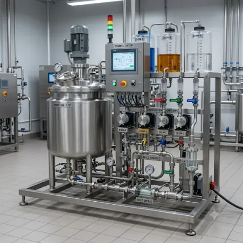
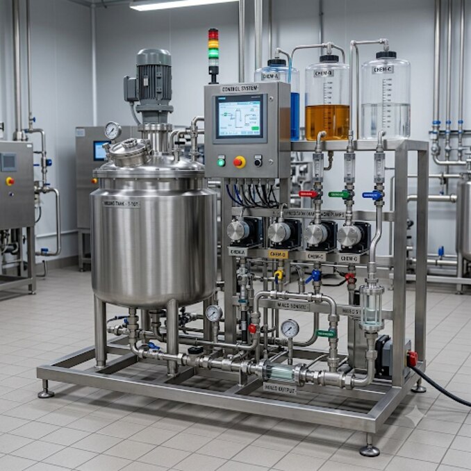
 | CHEMICAL MIXING AND DOSING SYSTEM CHEMICAL MIXING AND DOSING SYSTEM Chemical dosing is the adding of chemicals into water/fluid or sludge to achieve required conditioning. View product → |
Frequently asked questions
How do you calculate the chemical feed rate for a treatment system?
Multiply water flow by the target active dose. At 500 m³/h and 20 mg/L, the requirement is 10,000 g/h, or 10 kg/h of active chemical.
Which dosing control method suits changing water quality?
Use flow-paced dosing when demand follows water flow. Add feedback control when measurements such as pH, chlorine residual or oxidation-reduction potential change quickly.
How can you prove a dosing pump delivers its commanded dose?
Run a timed calibration test, compare the collected volume with the expected output, and check stroke length, speed, suction conditions and discharge pressure.
What should you check when choosing chemical dosing equipment?
Check chemical concentration, temperature, viscosity, compatibility and pressure before selecting the pump, tubing, valves, seals and injection quill.